
FAQ
1 Unit MQL Systems
1.1 What is the difference between MQL and ‘mist lubrication?’
1.1.1 How do I choose the best nozzle for my saw?
Saw nozzle options
Click here for more info Bat Nozzle
The Bat Nozzle was designed to easily fit on a wide variety of circular saws, vertical band saws, and horizontal band saws. The nozzle includes a 1.75” [44.5 mm] square mounting flange that can be attached to the blade guard. A 1” [25.4mm] diameter hole drilled through the guard allows the nozzle to be centered over the blade. The nozzle position can then be adjusted as close to the blade as required with a thumb screw. Two outlets on the sides of the blade and a third outlet spraying directly into the gullet of the teeth assure proper application of lubricant to the saw blade. The Bat Nozzle is available in various lengths to accommodate a broad range of saws.
Click here for more info Band Saw Blade Nozzle
The Band Saw Blade (BSB) Nozzle provides users with alternative mounting options and delivers an ideal spray pattern for horizontal band saw blade lubrication. Its smaller footprint makes for easier mounting and less intrusive installation. When mounted to the blade guide, proper positioning is easy when using the built-in ruler guide. Simply align the top of the blade with the appropriate blade size marking and secure the nozzle in place. For additional mounting flexibility, optional brackets are available. The BSB Nozzle is available in 1” [25.4 mm], 2” [50.8 mm], and 3” [76.2 mm] sizes to accommodate most common band saw blade widths.
Click here for more info Band Saw Guide Nozzle
When blade guide lubrication is required, the Band Saw Guide (BSG) Nozzle will lubricate the sides of the blade to help minimize friction. The BSG Nozzle can be mounted directly to a guide block or to the BSB Nozzle. When paired with a BSB Nozzle, this will provide lubrication for both the cutting edge and the sides of the blade.
Click here for more info Mounting kit
For maximum mounting flexibility, two mounting brackets are available for the bandsaw nozzles. The block mount allows either a blade or the guide nozzle to be held 90 degrees from the mounting surface. The rail mount allows the vertical height of the BSB or BSG Nozzles to be easily adjusted by sliding the nozzle up or down and tightening the clamp at the side.
Click here for more info Two mount options available
1. Block mount
2. Rail mount
1.2 For misting lubricants, what is the ratio of lubricant to water?
There is no mixing required when using our Coolube® lubricant. Coolube® is applied in aerosol form using an MQL applicator such as our Quantum™ system, Revolution™ system, Coolubricator™
Unist MQL System capable of delivering a constant and precisely metered atomized spray of lubricant
or Serv-O-Spray™
Unist MQL System capable of delivering an intermittent and precisely metered spray of lubricant. Ideal for intermittent machining operations such as tapping, drilling, etc.
systems.
1.1 About MQL systems
1.1.1 How do I choose the best nozzle for my saw?
Saw nozzle options
Click here for more info Bat Nozzle
The Bat Nozzle was designed to easily fit on a wide variety of circular saws, vertical band saws, and horizontal band saws. The nozzle includes a 1.75” [44.5 mm] square mounting flange that can be attached to the blade guard. A 1” [25.4mm] diameter hole drilled through the guard allows the nozzle to be centered over the blade. The nozzle position can then be adjusted as close to the blade as required with a thumb screw. Two outlets on the sides of the blade and a third outlet spraying directly into the gullet of the teeth assure proper application of lubricant to the saw blade. The Bat Nozzle is available in various lengths to accommodate a broad range of saws.
Click here for more info Band Saw Blade Nozzle
The Band Saw Blade (BSB) Nozzle provides users with alternative mounting options and delivers an ideal spray pattern for horizontal band saw blade lubrication. Its smaller footprint makes for easier mounting and less intrusive installation. When mounted to the blade guide, proper positioning is easy when using the built-in ruler guide. Simply align the top of the blade with the appropriate blade size marking and secure the nozzle in place. For additional mounting flexibility, optional brackets are available. The BSB Nozzle is available in 1” [25.4 mm], 2” [50.8 mm], and 3” [76.2 mm] sizes to accommodate most common band saw blade widths.
Click here for more info Band Saw Guide Nozzle
When blade guide lubrication is required, the Band Saw Guide (BSG) Nozzle will lubricate the sides of the blade to help minimize friction. The BSG Nozzle can be mounted directly to a guide block or to the BSB Nozzle. When paired with a BSB Nozzle, this will provide lubrication for both the cutting edge and the sides of the blade.
Click here for more info Mounting kit
For maximum mounting flexibility, two mounting brackets are available for the bandsaw nozzles. The block mount allows either a blade or the guide nozzle to be held 90 degrees from the mounting surface. The rail mount allows the vertical height of the BSB or BSG Nozzles to be easily adjusted by sliding the nozzle up or down and tightening the clamp at the side.
Click here for more info Two mount options available
1. Block mount
2. Rail mount
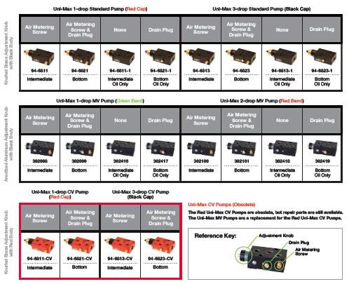
1.1.2 How can I tell which Unist pump I have?
There are several styles of Unist positive displacement pumps. The pump you have depends on several things including what type of fluid you are pumping and whether or not your pump is ‘stacked’ with other pumps. If your pump is one of several in a stack, its position in the stack determines its style. Consult the chart below (click on the image for larger view) to determine your pump style and type.
Click here for a video on our new MV (Multi-Viscosity) pumps which also has some good information on identifying all types of pumps.
1.2 System Setup
How do I convert ‘drops’ to milliliters or ounces?
Use the following chart to convert between drops, milliliters or ounces:
| Fluid Output Conversion Chart | |||||||
| mL/hr | oz/hr | drop/hr | mL/min | oz/min | drop/min | ||
| 2 | 0.07 | 60.00 | 0.03 | 0.00 | 1.00 | ||
| 3 | 0.10 | 90.00 | 0.05 | 0.00 | 1.50 | ||
| 4 | 0.14 | 120.00 | 0.07 | 0.00 | 2.00 | ||
| 5 | 0.17 | 150.00 | 0.08 | 0.00 | 2.50 | ||
| 6 | 0.20 | 180.00 | 0.10 | 0.00 | 3.00 | ||
| 7 | 0.24 | 210.00 | 0.12 | 0.00 | 3.50 | ||
| 8 | 0.27 | 240.00 | 0.13 | 0.00 | 4.00 | ||
| 9 | 0.30 | 270.00 | 0.15 | 0.01 | 4.50 | ||
| 10 | 0.34 | 300.00 | 0.17 | 0.01 | 5.00 | ||
| 15 | 0.51 | 450.00 | 0.25 | 0.01 | 7.50 | ||
| 20 | 0.68 | 600.00 | 0.33 | 0.01 | 10.00 | ||
| 25 | 0.85 | 750.00 | 0.42 | 0.01 | 12.50 | ||
| 30 | 1.01 | 900.00 | 0.50 | 0.02 | 15.00 | ||
| 35 | 1.18 | 1050.00 | 0.58 | 0.02 | 17.50 | ||
| 40 | 1.35 | 1200.00 | 0.67 | 0.02 | 20.00 | ||
| 40 | 1.35 | 1200.00 | 0.67 | 0.02 | 20.00 | ||
| 45 | 1.52 | 1350.00 | 0.75 | 0.03 | 22.50 | ||
| 50 | 1.69 | 1500.00 | 0.83 | 0.03 | 25.00 | ||
| 55 | 1.86 | 1650.00 | 0.92 | 0.03 | 27.50 | ||
| 60 | 2.03 | 1800.00 | 1.00 | 0.03 | 30.00 | ||
| 65 | 2.20 | 1950.00 | 1.08 | 0.04 | 32.50 | ||
| 70 | 2.37 | 2100.00 | 1.17 | 0.04 | 35.00 | ||
| 75 | 2.54 | 2250.00 | 1.25 | 0.04 | 37.50 | ||
| 80 | 2.71 | 2400.00 | 1.33 | 0.05 | 40.00 | ||
| 85 | 2.87 | 2550.00 | 1.42 | 0.05 | 42.50 | ||
| 90 | 3.04 | 2700.00 | 1.50 | 0.05 | 45.00 | ||
| 95 | 3.21 | 2850.00 | 1.58 | 0.05 | 47.50 | ||
| 100 | 3.38 | 3000.00 | 1.67 | 0.06 | 50.00 | ||
| 105 | 3.55 | 3150.00 | 1.75 | 0.06 | 52.50 | ||
| 110 | 3.72 | 3300.00 | 1.83 | 0.06 | 55.00 | ||
| 115 | 3.89 | 3450.00 | 1.92 | 0.06 | 57.50 | ||
| 120 | 4.06 | 3600.00 | 1.92 | 0.06 | 60.00 | ||
| 125 | 4.23 | 3750.00 | 2.08 | 0.07 | 62.50 | ||
| 130 | 4.40 | 3900.00 | 2.17 | 0.07 | 65.00 | ||
What is the right amount of air pressure/PSI that I need for my lubricator?
As a general rule of thumb, MQL applies between 5 to 80 mL/hour (0.2 to 2.5 oz./hour) on tools less than 40 mm (1.57”) in diameter. The amount is dependent on the specific cutting conditions, but fortunately there is usually a lot of latitude on what will work. To make it easy to adjust the output of a Coolubricator, it helps to fix two of the controls first so you only have to adjust one. The settings and process given here assume you are using Coolube and standard Unist nozzles. If you are not you may have to make additional adjustments to find the best setting for your operation.

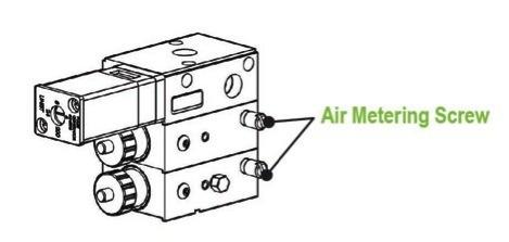
First, set the nozzle airflow. A properly adjusted MQL system uses just enough air velocity to drive the lubricant to the tool when it is cutting. Setting the air flow higher than necessary will create undesirable fogging of the fluid. On a Coolubricator system, the amount of air that mixes with fluid at the nozzle tip is adjusted with the air metering screw. Turn the metering screw counter-clockwise to increase the air flow and clockwise to decrease the air flow. A good initial setting is open from ¼ to ½ of a turn.
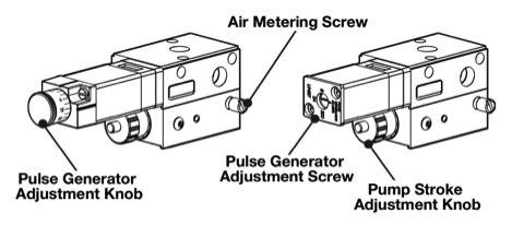
Next, set the pump to a half stroke. This procedure depends on the pump type.
On the standard Unist pumps, rotate the knob clockwise until it stops (full stroke), and then back it off (counter-clockwise) 3 full revolutions.
On the MV style pumps, rotate the knob counter-clockwise until it stops (full stroke), and then back it off (clockwise) 3.5 revolutions.
This middle position generally gives a good spray pattern from our standard nozzles and sets the output so it is easy to know the amount of fluid being dispensed.
Now you can now adjust the pulse generator to vary the amount of fluid dispensed. With the pump at half stroke, the output is approximately 1 mL/hour when the pulse generator is set to 1 cycle/minute. Knowing this, it’s easy to achieve other desired settings. For example, to get 40 mL/hour of output you turn the pulse generator knob so cycles 40 times per minute. Similarly, for 20 mL/hour set the pulse generator to 20cycles/minute.
Less is often more in MQL, so we suggest starting out on the lower end of the MQL range. Often somewhere around 20 mL/hour is a good starting point. As stated previously, this can be achieved with the pump at half stroke and the pulse generator set at 20 cycles/minute (once cycle every 3 seconds). This initial setting will work for most cases, but of course you may have to do some additional tweaking depending on your circumstances.
On the extreme ends of the MQL range, this single-knob adjustment approach may not give the best output results. If you find the fluid output appears to be pulsing with each pulse of the pulse generator, increase the pulse generator rate and correspondingly decrease the stroke of the pump to maintain the same total output. If the pulse generator sounds like a machine gun (more than 1 pulse/second), then decrease its rate and increase the pump stroke.
It is important to note that these adjustments are made once the pumps are primed and ready for use. The pump must be set to full stroke to prime properly and because of this they are set at full stoke when leaving the factory.
What should be the initial settings on my Coolubricator?
As a general rule of thumb, MQL applies between 5 to 80 mL/hour (0.2 to 2.5 oz./hour) on tools less than 40 mm (1.57”) in diameter. The amount is dependent on the specific cutting conditions, but fortunately there is usually a lot of latitude on what will work. To make it easy to adjust the output of a Coolubricator, it helps to fix two of the controls first so you only have to adjust one. The settings and process given here assume you are using Coolube and standard Unist nozzles. If you are not you may have to make additional adjustments to find the best setting for your operation.
First, set the nozzle airflow. A properly adjusted MQL system uses just enough air velocity to drive the lubricant to the tool when it is cutting. Setting the air flow higher than necessary will create undesirable fogging of the fluid. On a Coolubricator system, the amount of air that mixes with fluid at the nozzle tip is adjusted with the air metering screw. Turn the metering screw counter-clockwise to increase the air flow and clockwise to decrease the air flow. A good initial setting is open from ¼ to ½ of a turn.
Next, set the pump to a half stroke. This procedure depends on the pump type.
On the standard Unist pumps, rotate the knob clockwise until it stops (full stroke), and then back it off (counter-clockwise) 3 full revolutions.
On the MV style pumps, rotate the knob counter-clockwise until it stops (full stroke), and then back it off (clockwise) 3.5 revolutions.
This middle position generally gives a good spray pattern from our standard nozzles and sets the output so it is easy to know the amount of fluid being dispensed.
Now you can now adjust the pulse generator to vary the amount of fluid dispensed. With the pump at half stroke, the output is approximately 1 mL/hour when the pulse generator is set to 1 cycle/minute. Knowing this, it’s easy to achieve other desired settings. For example, to get 40 mL/hour of output you turn the pulse generator knob so cycles 40 times per minute. Similarly, for 20 mL/hour set the pulse generator to 20cycles/minute.
Less is often more in MQL, so we suggest starting out on the lower end of the MQL range. Often somewhere around 20 mL/hour is a good starting point. As stated previously, this can be achieved with the pump at half stroke and the pulse generator set at 20 cycles/minute (once cycle every 3 seconds). This initial setting will work for most cases, but of course you may have to do some additional tweaking depending on your circumstances.
On the extreme ends of the MQL range, this single-knob adjustment approach may not give the best output results. If you find the fluid output appears to be pulsing with each pulse of the pulse generator, increase the pulse generator rate and correspondingly decrease the stroke of the pump to maintain the same total output. If the pulse generator sounds like a machine gun (more than 1 pulse/second), then decrease its rate and increase the pump stroke.
It is important to note that these adjustments are made once the pumps are primed and ready for use. The pump must be set to full stroke to prime properly and because of this they are set at full stoke when leaving the factory.
2.1 About Uni-Roller® Systems
How fast can I run my press and still lubricate my stock effectively with a Uni-Roller system?
It depends on the lubricant in some cases, but a general guideline is that Uni-Roller® type C units can run up to 100 ft/min and Uni-Roller® type S units can run up to 500 ft/min.
How hard is it to get parts for my Uni-Roller® System?
Parts are in stock and in most cases can be sent out the next day.
How long can I expect my Uni-Roller system’s roller covers to last?
Usually 9 months, although it depends on the application and the condition of the metal (burrs on the edges will damage the covers and shorten their lifespan)
How long does it take from the time I order my Uni-Roller system until it ships?
Usually 2-3 weeks
Is there a battery in my SPR-2000® control panel?
No, there is no battery in the panel. However, all of the systems data is stored in an EEPROM so there should be no loss of data in the event of a power failure.
What are the limitations of flow sensors?
Flow sensors can be used to monitor the flow from a valve each time it is actuated. They work by watching for flow every time a valve is actuated and then transmitting a signal to the system . Once the system has confirmed flow, it doesn’t monitor the flow sensor again until the next valve cycle. As a result, if the duration is quite long, and flow is confirmed within the first .5 second, the system would not detect it if the flow stopped after that time until the next cycle. Another limitation is that the sensors can not differentiate between the flow of fluid or air. As a result, if the fluid reservoir runs dry so air is flowing through the valve instead of fluid, it would not create an alarm. In this case, a low level switch in the fluid reservoir would detect the problem. One other limitation is that since a flow sensor requires some time to sense flow, it is usually not possible to detect flow for a duration of less than about 250 milliseconds.
What is the ROI on a Unist Uni-Roller® system?
Our Uni-Roller® systems deliver return on investment in less than six months. That’s what many of our customers report. By applying the proper amount of fluid, Uni-Roller® uses 50 to 90% less lubricant. Plus it decreases the mess, the parts cleaning, fluid recycling and costs associated with in-die spray systems, rag technology and externally lubricated rollers.
Which rollers are best for my application? Does the viscosity of the oil matter?
The correct rollers for your application depend on your fluid of choice. In most cases, our polyester felt roller covers will offer the best performance. For vanishing oils and for thin stock that is narrower than the overall width of the roller, our polyurethane foam roller covers may be a better choice. Viscosity of the fluid plays a small role but there are other factors to consider. Contact Unist with details on your specific application and fluid type and we’ll be happy to make a recommendation!
Will my fluid work with a Uni-Roller system?
Contact us. We may have already tested your particular fluid. We have a database that includes hundreds of fluids we’ve tested. If we haven’t tested your fluid, send us a sample for us to test for you.
3. MQL
Has MQL proven to extend tool life as well as the top rated water soluble flood coolants, in turning operations with carbide inserts on steel?
Yes, MQL can work well in turning applications. However there are some special considerations that need to be addressed. Since the cuttingedge of the tool is continuously in the cut, nozzle position is critical and more difficult. Carbide tools can work well, but it is largely determined by the relative size of the parts and the length of time in the cut. In many cases a multi-layer coating, such as TiAlN works even better
I am getting a mist and it is bothering my employees. What do I do?
Machining with minimum quantity lubrication has been shown to produce fewer emissions than flood cooling. It is, in fact, a low-emission process. Unfortunately, when starting with MQL, many shops think that more is better so they blast as far too much air through the MQLnozzles and literally create a fog or mist of lubricant in the air. This is not MQL! A properly adjusted MQL system uses just enough air velocity to drive the lubricant to the tool, not enough to drive it around the block!
Just as less is better with the air, closer is better with the nozzle. The longer the distance that the nozzle needs to spray, the more airflow is needed to carry aerosol and the higher the likelihood of an unwanted mist being generated. In closed machines, an extraction system can help with this. In open systems, putting the nozzle closer to the cut helps. The fluid output should be virtually invisible. If you see a mist spraying from an external nozzle, you will likely see fogging in the plant.
Unless you are working with very small chips, as in micro-cutting, trying to blow the chips away with air from the fluid delivery spray will only create a fog and use more fluid than is necessary. Use a separate chip removal approach, such as an air blow-off or a vacuum, to remove chips if needed.
On a Coolubricator or Serv-O-Spray system the amount of air that mixes with fluid at the nozzle tip can be adjusted with the air metering screw. Turn the metering screw counter-clockwise to increase the air flow and clockwise to decrease the air flow. A good initial setting is open about from ¼ to ½ of a turn.
Is MQL the same as traditional flood coolant?
Minimum Quantity Lubrication (MQL) is not the same as traditional flood coolant. In fact, it is very different. Many people new to MQL are used to a flood coolant mindset and have trouble making the distinctions:
- MQL does not use a coolant. Traditional flood coolant uses a circulated liquid designed for heat transmission to carry heat away from the interface of the cutting tool and the work piece.
- MQL uses a lubricant. With MQL, friction is reduced within the cutting tool/work piece interface through the use of a lubricant. Advanced lubricants such as Coolube reduce friction, and therefore heat, so well that there is no need to carry heat away using a coolant.
- Coolant uses a flood. For coolant to work, the interface must be flooded with coolant which must then have a place to go when it has done its job and absorbed the heat. This requires constant recirculation of gallons and gallons of coolant.
- MQL uses minimum quantities. Advanced MQL lubricants do their job so well that typically, only a few ounces are used during an 8 hour shift
- Coolant requires extra equipment. Because coolant is re-used until it is no longer viable, it requires equipment to recirculate and filter/clean it. Sump-side coalescers, skimmers, filters, sump vacs, and test kits are common equipment required for the use of coolant.
- MQL requires minimum equipment. With MQL, you need a quality applicator such as a Unist Coolubricator or Serv-O-Spray which has the ability to accurately dispense lubricant and to do it consistently. There is no need for any additional equipment.
- Flood coolant is not a sensitive process. Applying coolant is a simple process. As long as enough coolant is applied to flood the interface, it will work.
- MQL requires hitting a lubrication ‘sweet spot.’ With Minimum Quantity Lubrication, each cutting operation has an appropriate amount of lubricant or ‘sweet spot’ which must be hit to experience MQL‘s benefits. Luckily, adjusting your MQL applicator to hit the sweet spot is simple when you follow some basic guidelines.
- Coolant is anything but dry. Coolant tends to splash and get thrown from the interface. This can result in a mess with coolant coating equipment, parts, chips/swarf, and floors. Since coolant remains after the cutting process, it can create secondary messes during its filtration or disposal phases.
- MQL is near-dry. Such a small quantity of lubricant is applied in MQL that there is no mess to clean up. When applied properly, only a very thin film of lubricant remains on finished parts and chips/swarf are virtually dry meaning they can be recycled for greater profit. With MQL, your equipment and floors stay clean.
- Coolant requires disposal. Once coolant is no longer usable, it requires costly disposal
- MQL lubricants are consumed No excess MQL lubricant remains to require disposal or clean up.
- Coolant is cheap per gallon but an expensive process to maintain. When you consider the additional equipment required to utilize coolant, the increased housekeeping costs, and disposal costs, coolant quickly becomes an expensive proposition.
- MQL is an inexpensive process to maintain. MQL lubricants are more expensive than coolants per gallon. This may be true, but when you consider that only ounces are used per shift, you see that a gallon can go a long way. When you factor in the benefits of MQL in reduced housekeeping, cleaner parts, increased chip/swarf recycling values, healthier employees, and reduced equipment costs, MQLquickly becomes a less expensive proposition than coolant
4. Coolube® Lubricants
Does Coolube® irritate the skin?
As with many natural products, prolonged exposure to Coolube’s® bears a slight risk of skin irritation, but this is extremely rare. Most of the components of Coolube are also used in cosmetics, and this is one of the reasons it rarely irritates the skin. The components are also food-grade and, although Unist does not recommend it, could be used in food preparation.
In over 30 years of manufacturing and handling Coolube® we have had very, very few reports of any exposure issues. However if irritation should occur, washing the affected area with soap and water should eliminate the irritation. It is worth noting that one of Coolube’s® components is considered a penetration enhancer and may enhance the skin penetration of other chemicals. For this reason users should exercise caution when using Coolube® in conjunction with other products which have set limits based on dermal absorption.
For misting lubricants, what is the ratio of lubricant to water?
There is no mixing required when using our Coolube® lubricant. Coolube® is applied in aerosol form using an MQL applicator such as our Quantum™ system, Revolution™ system, Coolubricator™ or Serv-O-Spray™ systems.
How do you clean up residual Coolube from parts?
Cleaning residual Coolube from parts
In most cases there should be little if any Coolube left on the part. If the part has much oil on it, it may be an indication that means the MQL spray needs adjusting. But in the cases where over spray is unavoidable, or there can be no oil on the part at all, Coolube is easy to wash off.
Coolube is oil, so a simple alkaline based detergent is sufficient for cleaning. Alkaline cleaners are commonly used for cleaning metal and are designed to remove grease and oils. Dish soaps are examples of mild alkaline cleansers that would work well work with Coolube, as would most other alkaline based industrial detergents that may already be available in your shop.
How does the EP Additive Work in 201EP?
The Extreme Pressure (EP) additive in Coolube 2210 EP helps to decrease the wear of tools exposed to very high pressures. The term “extreme pressure” classically refers to the property of lubricants which impart to rubbing surfaces the ability of carrying appreciably greater loads than would be possible with ordinary lubricants without excessive wear or damage.
Our EP additive contains organic sulfur compounds which react with metal surfaces based on the heat generated by small irregularities on the surfaces. These irregularities cause localized flashes of high temperature without significant increase of the overall average surface temperature. When these conditions exist the additive reacts to produce a protective film that prevents this friction thus enhancing tool lifeand improving surface finishes.
Sulfur containing EP additives can cause corrosion problems in parts made of bronze, brass and other copper alloys when high temperature environment is encountered. This is why we only recommend Coolube 2210 EP for use on ferrous metals.
If I am using Coolube, what paint should I use on my machine so it doesn’t come off?
Coolube® is a highly refined plant-based oil and should not affect the paint on your machine. Coolube® can be easily cleaned using an alkaline-based detergent (such as ‘Dawn’ dish washing liquid).
AIs Coolube® biobased?
Defined by the 2002 Farm Bill, biobased products are commercial or industrial products (other than food or feed) that are composed in whole, or in significant part, of biological products, renewable agricultural materials (including plant, animal, and marine materials), or forestry materials. The USDA issues Certified Biobased Product labels to products with a minimum of 25% biobased content. Coolube® 2210 is certified at 93% biobased content and Coolube® 2210EP at 92%.
What is the difference between Coolube® 2210 and Coolube® 2201EP?
Coolube® 2210 is ideal for metals, wood, rubber, and most plastics and is especially effective on aluminum and non-ferrous metals.
Coolube® 2210EP contains an ‘Extreme Pressure’ additive and is specially formulated for use with ferrous metals. Coolube® 2210EP also works with all non-ferrous metals except copper.